

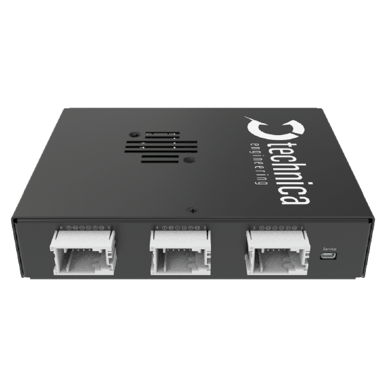

The Capture Module 10BASE-T1S is a specialized logging device for capturing and timestamping 10BASE-T1S Ethernet traffic. It offers advanced monitoring capabilities, recording key bus events such as beacon receptions and empty cycles. Designed for minimal interference, it ensures precise traffic capture and provides an accurate representation of network behavior for detailed analysis.
Contact Us
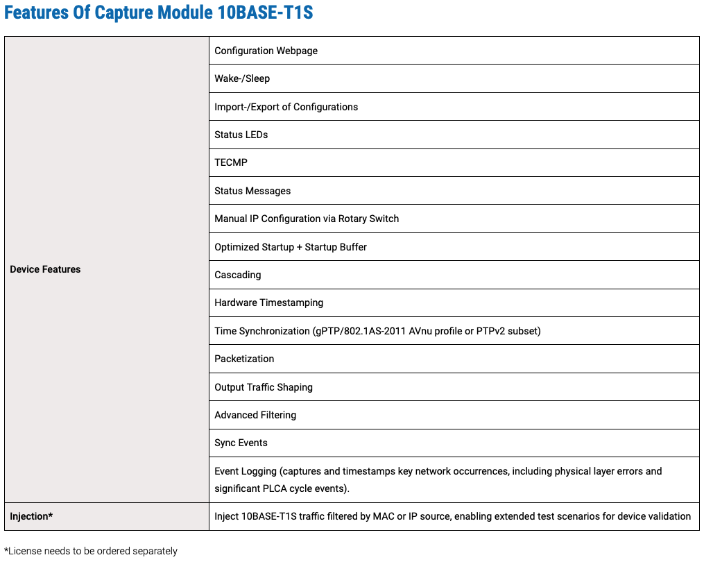
The CM offers a flexible and user-friendly configuration through its built-in web server. The device webpage can be easily accessed via a standard web browser. In addition, the possibility to import/export a configuration makes it even more convenient.
Early Access Product
An Early Access Product (EAP) is a nearly finished product available to selected users before its official release. The product may remain in this status, because it includes a pre-market component (PHY/Switches) that is not fully certified, which restricts the entire product from achieving CE certification or equivalent regulatory approval. This means, EAP is still a prototype, but in a very advanced state. Small adaptations are still possible, but no critical changes are expected and general development is closed. The software includes almost all planned features. Documentation as e.g. User Manual is available and completed.

Capture Modules are designed to be used in different environments such as in the car, on a development desk or in testbenches. In order to cover these areas as best as possible, the devices allow continuous operation and a wide temperature range.


In the TECMP Status Messages “Status bus” of the device you can find the link quality of each port, next to other information
In a multidrop bus, the “stub” is any short connection branching off the main bus. Stub lines are local wires to each device.
When a port is used as an injector, the “PLCA Enabled” flag is set to 1, else it is 0.
The PHYs are working in a passive mode and doesn’t take part in the PLCA cycle.
The current Symbol count is only counting BEACONs. Also, in future releases only the BEACONs will be counted.
It is guaranteed that it works always with stub lines lower than 10cm, longer stub lines can still be fine, setup dependent, but not guaranteed.
Proper operation is guaranteed for stub lines below 10 cm. Longer stub lines may work, depending on the setup, but are not guaranteed.?
This is expected behavior. Once a port is configured for traffic injection, it is dedicated to transmit and cannot support logging or packet capture functions simultaneously. The port is an active part of the 10BASE-T1S BUS.
while there is no direct or specific error message or LED indicator that explicitly signals malformed PLCA topologies (such as duplicate Node IDs or multiple Coordinators), these misconfigurations can cause side effects—like collisions or decoding errors—that may trigger the general error LED on the device. However, these conditions often lead to side effects like:
The Capture Module, in combination with Event Logging feature, becomes a powerful tool to identify such issues:
In short, while there’s no single TECMP field stating “malformed topology”, you can infer such problems with high confidence by combining:
Yes, with following conditions:
Please check following:
When the PLCA coordinator (Node ID = 0) is not present in the network, the devices cannot execute PLCA arbitration.
Fall Back: Instead, they fall back to a basic CSMA/CD-like (Carrier Sense Multiple Access with Collision Detection) mechanism, often referred to internally as CSDM:
A rising “Collisions Tx” value often indicates an issue with the physical setup, rather than actual protocol-level collisions.
In a properly configured PLCA (Physical Layer Collision Avoidance) network, physical collisions should never occur, as only one node is allowed to transmit at a time. This is managed by PLCA’s in-band signaling and timing coordination.
If the bus is not correctly terminated or if the impedance of the network is not within specification, the device may interpret the resulting signal reflections or disturbances on the line as a collision. This is because the physical characteristics of the signal in such cases can resemble the condition of two nodes transmitting simultaneously. Since the device cannot reliably differentiate between an actual simultaneous transmission and a poor bus condition, it increases the “Collisions Tx” counter accordingly.
Below is the list of theoretical PLCA cycle times for node Counts from 1 to 8 following assumptions:
This is because the MAC requires a minimum inter-packet gap (IPG) of 9.6 μs, which cannot be achieved when using 64-byte packets with Node Count = 1 or 2.
In the specific case with only two active nodes (Node Count = 1 effectively means two devices in the network), the performance with or without PLCA should be quite similar—assuming there are no collisions. In such a scenario, the communication can operate close to the line rate even in CSMA/CD mode.
Main difference is that each node gets a unique MAC address. Further information can be found in the User Manual.
Yes. For more details, please check the UM.

Are you looking for support?

Need more information about our products?
