

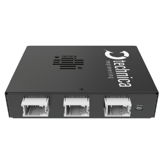

Das Capture Module 10BASE-T1S ist ein spezielles Logging-Gerät zum Erfassen und Zeitstempeln von 10BASE-T1S-Ethernet-Verkehr. Es bietet erweiterte Überwachungsfunktionen und zeichnet wichtige Busereignisse wie Signalempfänge und Leerzyklen auf. Es wurde für minimale Interferenzen entwickelt, gewährleistet eine präzise Erfassung des Datenverkehrs und bietet eine genaue Darstellung des Netzwerkverhaltens für detaillierte Analysen.
Contact Us
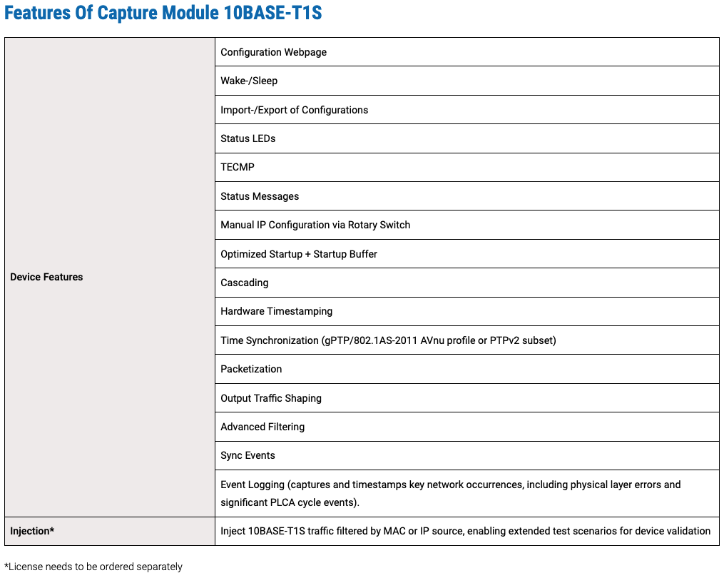
Das CM bietet über seinen eingebauten Webserver eine flexible und benutzerfreundliche Konfiguration. Auf die Geräte-Webseite kann einfach über einen Standard-Webbrowser zugegriffen werden. Darüber hinaus macht es die Möglichkeit, eine Konfiguration zu importieren/exportieren, noch komfortabler.
Early-Access-Produkt
Ein Early-Access-Produkt (EAP) ist ein fast fertiges Produkt, das ausgewählten Benutzern vor seiner offiziellen Veröffentlichung zur Verfügung steht. Das Produkt kann diesen Status beibehalten, da es eine Komponente enthält, die noch vor der Markteinführung verfügbar ist (PHY/Switches), die noch nicht vollständig zertifiziert ist, sodass das gesamte Produkt keine CE-Zertifizierung oder eine gleichwertige behördliche Zulassung erhalten kann. Das bedeutet, dass es sich bei EAP immer noch um einen Prototyp handelt, der sich jedoch in einem sehr fortgeschrittenen Stadium befindet. Kleine Anpassungen sind noch möglich, aber es werden keine kritischen Änderungen erwartet und die allgemeine Entwicklung ist abgeschlossen. Die Software beinhaltet fast alle geplanten Funktionen. Die Dokumentation wie z. B. das Benutzerhandbuch ist verfügbar und vollständig.

Capture-Module sind für den Einsatz in verschiedenen Umgebungen konzipiert, z. B. im Auto, auf einem Entwicklungstisch oder in Prüfständen. Um diese Bereiche bestmöglich abzudecken, ermöglichen die Geräte einen Dauerbetrieb und einen weiten Temperaturbereich.


In the TECMP Status Messages “Status bus” of the device you can find the link quality of each port, next to other information
In a multidrop bus, the “stub” is any short connection branching off the main bus. Stub lines are local wires to each device.
When a port is used as an injector, the “PLCA Enabled” flag is set to 1, else it is 0.
The PHYs are working in a passive mode and doesn’t take part in the PLCA cycle.
The current Symbol count is only counting BEACONs. Also, in future releases only the BEACONs will be counted.
It is guaranteed that it works always with stub lines lower than 10cm, longer stub lines can still be fine, setup dependent, but not guaranteed.
Proper operation is guaranteed for stub lines below 10 cm. Longer stub lines may work, depending on the setup, but are not guaranteed.?
This is expected behavior. Once a port is configured for traffic injection, it is dedicated to transmit and cannot support logging or packet capture functions simultaneously. The port is an active part of the 10BASE-T1S BUS.
while there is no direct or specific error message or LED indicator that explicitly signals malformed PLCA topologies (such as duplicate Node IDs or multiple Coordinators), these misconfigurations can cause side effects—like collisions or decoding errors—that may trigger the general error LED on the device. However, these conditions often lead to side effects like:
The Capture Module, in combination with Event Logging feature, becomes a powerful tool to identify such issues:
In short, while there’s no single TECMP field stating “malformed topology”, you can infer such problems with high confidence by combining:
Yes, with following conditions:
Please check following:
When the PLCA coordinator (Node ID = 0) is not present in the network, the devices cannot execute PLCA arbitration.
Fall Back: Instead, they fall back to a basic CSMA/CD-like (Carrier Sense Multiple Access with Collision Detection) mechanism, often referred to internally as CSDM:
A rising “Collisions Tx” value often indicates an issue with the physical setup, rather than actual protocol-level collisions.
In a properly configured PLCA (Physical Layer Collision Avoidance) network, physical collisions should never occur, as only one node is allowed to transmit at a time. This is managed by PLCA’s in-band signaling and timing coordination.
If the bus is not correctly terminated or if the impedance of the network is not within specification, the device may interpret the resulting signal reflections or disturbances on the line as a collision. This is because the physical characteristics of the signal in such cases can resemble the condition of two nodes transmitting simultaneously. Since the device cannot reliably differentiate between an actual simultaneous transmission and a poor bus condition, it increases the “Collisions Tx” counter accordingly.
Below is the list of theoretical PLCA cycle times for node Counts from 1 to 8 following assumptions:
This is because the MAC requires a minimum inter-packet gap (IPG) of 9.6 μs, which cannot be achieved when using 64-byte packets with Node Count = 1 or 2.
In the specific case with only two active nodes (Node Count = 1 effectively means two devices in the network), the performance with or without PLCA should be quite similar—assuming there are no collisions. In such a scenario, the communication can operate close to the line rate even in CSMA/CD mode.
Main difference is that each node gets a unique MAC address. Further information can be found in the User Manual.
Yes. For more details, please check the UM.

Suchen Sie Unterstützung?

Benötigen Sie weitere Informationen zu unseren Produkten?
