Technica Devices: Quick Start Guide

Enhanced Ethernet Switches (EES)

How to open the configuration webpage

1
Connecting the power cable

Connect red cable to VBAT+ (pin 7 or 8) and black cable to GND (pin 1 or 2). See reference image below for the relevant connector.

Requirements for the device power supply: typically 12 V. For more details refer to the User Manual

2
Connecting to PC

Connect an RJ45 cable from the PC to the host port / 100 BASE-TX of the EES. See reference image below for the relevant connector.

3
PC network adapter setup

As vehicle architectures become increasingly software-defined and connected, cybersecurity is no longer an isolated feature. It is a foundational layer of the entire system 10.0.0.XX   with subnet mask 255.255.255.0

Example Host IP: 10.0.0.15
Subnet Mask:  255.255.255.0
4
Configuration webpage access

To access the configuration webpage, Enter the IP address 10.0.0.200 your standard web browser.

URL: http://10.0.0.200
For more details regarding the switch refer to the User Manual available on the customer portal:
Capture Modules (CM)

High-Speed Logging & Rotary Switch Addressing Setup

1
Connecting the power cable

Connect red cable to VBAT+ (pin 1) and black cable to GND (pin 2). See reference image below for the relevant connector.

Requirements for the device power supply: typically 12 V. For more details refer to the User Manual

2
Connecting to PC

Connect an RJ45 cable from the PC to GB A. See reference image below for the relevant connector.

3
Configuration of device IP

Once connected with the RJ-45 port, please go to the network adapter settings and adjust the IP in the same range as your Capture Module.

Enter an IP in the same network, for example 10.104.3.XX  with subnet mask 255.255.255.0

Example Host IP: 10.104.3.20
Subnet Mask:  255.255.255.0
Notice: Do not assign any IP from the rotary switch table on the bottom label to avoid IP collisions.
4
Setting the rotary switch position

Set the rotary switch (IP Config) to position 0. Each rotary switch position is linked to an IP address in the table on the label on the bottom ofthe device. Use the IP shown on the label for position 0. See reference image below for Rotary switch.

5
Configuration webpage access
To access the position 0, enter the IP address as shown on the label at the bottom of the device.
URL: http://10.104.3.144

The above URL is an example based on rotary switch position 0, specifically for CM1000 High. For other Capture Modules, refer to rotary switch position on your device.

Alternative Connection Path

The configuration webpage can also be reached over the Host / Config port with the default IP 192.168.0.49. In this case set the PC to 192.168.0.x (x not 49) with subnet mask 255.255.255.0.

For more details regarding the switch refer to the User Manual available on the customer portal:
MediaConverters (MC)

Physical Layer Converter • Serial Console over USB

Architecture Notice
The MC has no webpage, but provides a console to interact with the device and dynamically reconfigure it. To access the console you have two options. Either use the MediaConverter app (available in the Customer Portal) or a terminal application like Tera Term.
Option A: MediaConverters app
1
Connecting the power cable

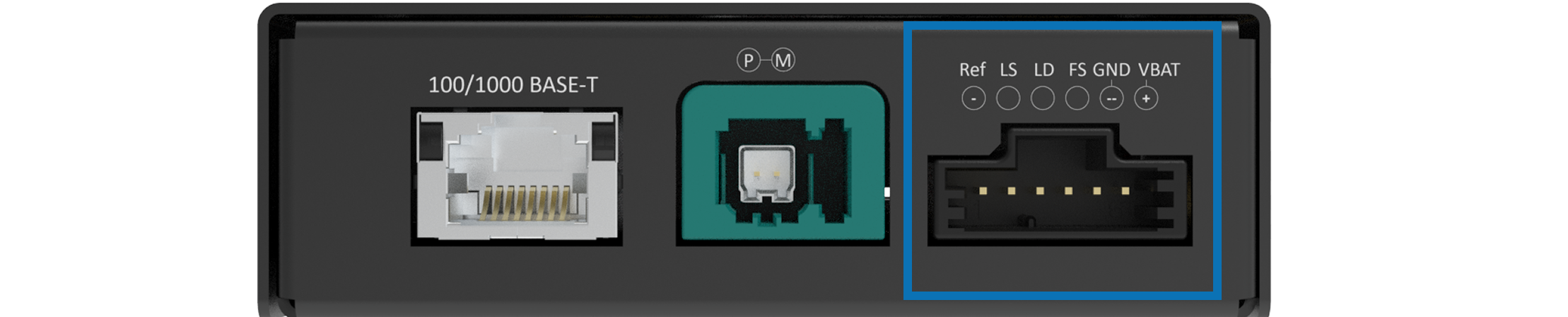
Connect red cable to VBAT+ (pin 6) and black cable to GND (pin 5). See reference image below for the relevant connector.

Requirements for the device power supply: typically 12 V. For more details refer to the User Manual
2

Connect the MC to the PC with the USB cable.

3

Open the app and select USB serial port.

4

Select the device serial number and click Open port.

Option B: Tera Term
1

Open Tera Term and go to File → New connection

2

Select Serial and choose the device's USB COM port.

3

Click OK and the console opens.

For more details regarding the MC or the MC app, refer to the User Manual available on the customer portal:
Network Interfacer (NI)

Automotive Protocol Interfacer • BASE-T/BASE-T1 Host Port Setup

1
Connecting the power cable

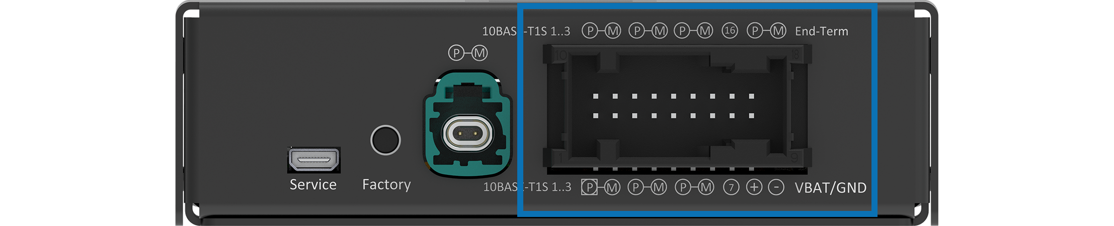
Connect red cable to VBAT+ (pin 8) and and black cable GND (pin 9). See reference image below for the relevant connector.

Requirements for the device power supply: typically 12 V. For more details refer to the User Manual
2
Connecting to PC

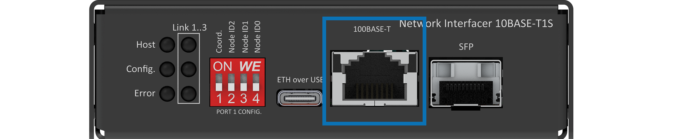
Connect an RJ45 cable from the PC to 100BASE-T/Host port. See reference image below for the relevant connector. You can also connect to Network Interfacer BASE-T through the USB-C or SFP port.

3
PC network adapter setup

Once connected with the RJ-45 port, please go to the network adapter settings and adjust the IP in the same range as your Network Interfacer. For example, 10.0.0.XX  with subnet mask 255.255.255.0

Example Host IP: 10.0.0.25
Subnet Mask:  255.255.255.0
4
Web browser access

To access the configuration webpage, Enter the IP address 10.0.0.200  your standard web browser.

To get access to the configuration webpage, open a browser and enter the IP 10.0.0.100

URL: http://10.0.0.100
For more details regarding the Network Interfacer, refer to the User Manual available on the customer portal:
CHOOSE YOUR DEVICE: